 English
 العربية
 Български
 Čeština
 Dansk
Dansk Nederlands
 Suomi
Suomi Français
 Deutsch
 Magyar
 Italiano
 日本語
日本語 한국어
한국어 Português
 Română
 Русский
 Slovenščina
 Español
 Svenska
 Tiếng Việt
The crimping quality inspection of the connecting harness terminal needs to be comprehensively evaluated from multiple dimensions such as appearance, size, mechanical properties, electrical properties and environmental adaptability. The specific inspection points are as follows:
1. Appearance inspection
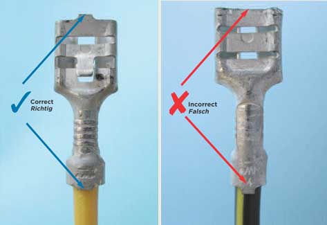
Terminal integrity: Check whether the terminal is bent, deformed or cracked to ensure that there is no mechanical damage after crimping.
Insulation layer status: Observe whether the insulation crimping is wrapped correctly to avoid piercing the insulation layer or insulation extrusion deformation.
Burr control: The burr height at the end of the crimping wing should be ≤1 times the material thickness, and the width should be ≤0.5 times the material thickness.
Brush visibility: Confirm that the metal wire (brush) of the wire core is visible after crimping and does not invade the inside of the connector.
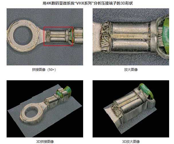
Observation and quantitative evaluation of wire harnesses and crimp terminals – conductors and core wires
2. Dimension parameter inspection
Crimp height: Adjust according to the terminal or mold manual, and the tolerance range must meet the requirements of the standard table.
Crimp width: The measurable crimp width (Cwm) should be controlled between 1Cw~1.1Cw, and the tolerance refers to the manufacturer’s specifications. Support angle: The maximum angle of the conductor crimping wing tangent relative to the vertical line is ≤30°.
Support height: The mutual support height of the crimping wings is ≥1/4 of the material thickness and ≥0.1mm.
Stripping length: Calculated according to the formula (L=0.5~1.0+A+B/2), ensure that there is no broken wire or shape damage at the end of the wire.
Crimping and crimping quality inspection of automotive wiring harness terminals
Key Inspection Points:
Terminal Integrity:
Look for any signs of damage, bending, or deformation of the terminal itself, indicating a potential issue during crimping.
Insulation Crimp:
Ensure the insulation is properly wrapped around the terminal, without any piercing of the wire or insulation.
Wire Strand Placement:
Verify that the wire strands are fully seated within the terminal barrel, with no protruding strands beyond the crimp area.
Bell Mouth:
The bell mouth (the flared edge of the terminal barrel) should be visible and properly formed, ensuring a good connection.
Crimp Height:
The height of the crimp should be within the specified range for the terminal and wire size, indicating proper compression.
Methods for Inspection:
Visual Inspection:
A magnifying glass or microscope can be used to closely examine the crimp for any defects.
Pull Force Test:
Apply a controlled pull force to the crimped wire and measure the resistance to determine the crimp’s strength.
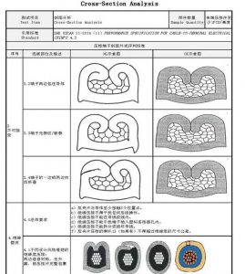
Cross-Section Analysis:
Cutting through a crimped terminal and examining the cross-section can reveal internal defects or improper crimping.
Bending Test:
Bend the wire several times to assess the stability of the insulation crimp.
Electrical Testing:
Use a continuity tester to check for electrical disconnections or short circuits.
Standards and Guidelines:
Industry standards like IPC and WHMA provide guidelines for crimp quality, including pull force requirements and crimp height specifications.
Specific crimping tools and techniques should be used to ensure consistent and reliable crimp quality.
Regular calibration of crimping tools is essential for maintaining accurate and reliable crimping.
III. Mechanical performance test Pull-out force test: Verify the crimping strength through a standard tensile test to ensure that the terminal is firmly connected to the harness.
Crimping wing symmetry: The crimping wing is allowed to be not completely symmetrical, but the end distance must be ≤1 times the material thickness.
IV. Electrical performance test Resistance test: Measure the resistance at the crimping point to ensure that the electrical connection is low impedance and stable.
Voltage drop test: Combined with profile analysis, verify whether the conductivity of the crimping point meets the requirements.
5. Environmental adaptability verification
Environmental resistance test: simulate high temperature, corrosive or humid environment to evaluate the waterproofness, heat resistance and corrosion resistance of the crimping point.
6. Other precautions
Tool matching: use the crimping die that matches the terminal model to avoid poor crimping due to improper tools.
Staff operation specifications: strengthen the training of new employees to reduce the crimping position deviation or distortion caused by unskilled technology.
Electrical performance of automotive wiring harnesses and crimp terminals
Through the above systematic inspection, the reliability of terminal crimping and product life can be effectively guaranteed, and the system risk caused by connection failure can be reduced.
This article mainly introduces the technical requirements, diagrams and test methods for terminal crimping quality, as well as graphic and text standards. It is recommended to bookmark the YAXUN wiring harness engineer website.
Conductor Crimping of Wire Harness Terminals:
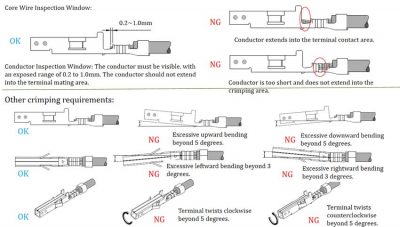
Terminal crimping bell mouth: There are bell mouths at both ends of the conductor crimping area or near the end of the insulation. The length is between 0.1mm~1/5 the length of the crimping area.
Wire core fixation: All wire cores (conductors) are stored in the conductor crimping area. The wire core breakage meets the following criteria: no breakage for ≤20 cores, less than 5% for >20 النوى, and no cores flying out.
The front core of the wire harness is exposed: the end of the wire core can be seen at the front of the conductor crimping area. The exposed length of the front core is between 0.5~1.5mm and does not affect the terminal fit.
Note: Not available with flag terminals.
Conductor crimping: The conductor crimping area is neatly crimped, and there are no problems such as core exposure or damage in the middle seam. Curl claw misalignment ≤0.3mn.
Insulation crimping of wire harness terminals
Insulation skin length: The insulation skin and wire core can be seen between the insulation crimping area and the conductor crimping area, and the insulation skin length is >1/3c~≤1C. Note: If the insulation length = 1C and it is in contact with the conductor crimping area, the wire core can be observed by pushing back the end of the insulation.
Insulation crimping: The insulation crimping area and the insulation skin match well, without deformation, and the curl claw misalignment is ≤0.3mm.
The crimping quality inspection of the connecting harness terminal
Terminal deformation:
The terminal is bent upward and downward: the terminal mating area and the crimping area are straight, and the bending angle is ≤3°.
The terminal is bent left and right: the terminal mating area is aligned with the central axis of the crimping area, and the deviation angle is ≤5°.
Twist: The center seam of the insulation crimp is aligned with the axis of the conductor crimp, and the degree of twist should be ≤5°.
For the insulation bending fixed terminal, at a distance of 50mm from the conductor crimping area, perform an insulation bending test for five cycles (bending 45° → bending 90° in the opposite direction → reset, as one cycle) according to Figure 3. No pulling force is exerted on the lead during the test. After the test, the insulation crimping was good and the insulation skin did not come out from the insulation crimping area.
(2) Insulation crimping section
(3) Measurement method of crimping height and width: crimping width is measured with a caliper (accuracy: 1/100); crimping height is measured with a crimping height micrometer (accuracy: 1/1000), as shown in Figure 5.
(4) Profile analysis method
• Use special cutting equipment to cut the conductor crimping area and insulation crimping area respectively according to Figure 6. When cutting, cut vertically and longitudinally in the middle of the crimping area, and avoid the grooves (reinforcing ribs) in the conductor crimping area.
• The cut section should be flat and without deformation, and the curl should not be opened.
• After cutting, polish the section to remove burrs. When polishing, be careful not to damage the section (such as curling, cracking, إلخ.).
• The polished section is coated with ferric chloride solution (content: 35%-45%) to clearly display the outline of the wire core and terminal wall.
• Use an electron microscope and calibrated profile analysis software to analyze and measure the relevant parameters of the profile.
Note: If the terminal is difficult to fix or cut, and problems such as cross-sectional deformation or curling occur during polishing, the terminal can be solidified in resin before polishing.
(2) Tensile test method
• According to the test method in Figure 7, release the insulation crimping, remove the insulation about 200mm away from the conductor crimping area, and reversely weld the conductor end to the conductor to form a stretch ring.
• After fixing the terminal with a special clamp and keeping the lead and conductor crimping area in a straight state, conduct a tensile test on the tension ring.
• Explosive force should not be used during the test. The test can be carried out by a tensile testing machine, and the moving speed of the machine head is between 25-50mm/min. During the test, observe and record the maximum tensile force value of the conductor, which should comply with the regulations of its wire diameter.
• Double-wire compression should be tested on each conductor one by one.