 English
 العربية
 Български
 Čeština
 Dansk
Dansk Nederlands
 Suomi
Suomi Français
 Deutsch
 Magyar
 Italiano
 日本語
日本語 한국어
한국어 Português
 Română
 Русский
 Slovenščina
 Español
 Svenska
 Tiếng Việt
The compatibility of FFC/FPC connectors is mainly reflected in the following aspects:
1. Specification matching
Number of pins and spacing
The number of pins and spacing of FFC/FPC connectors must be fully matched with the corresponding cables or circuit boards. Common spacings include 0.3mm, 0.5mm, 1.0mm, etc., which need to be selected according to the specific application scenario.
Contact end type
Type A (exposed contacts on the same side) or type D (exposed contacts on opposite sides) connectors need to be selected according to the cable contact position to ensure the accuracy of electrical contact.
 The difference between FFC connector and FPC connector |
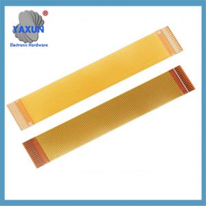 Custom FFC FPC Cable 0.3mm Pitch 4~ 51 Pin 60mm Flexible Flat Ribbon Cable for LCD Screen |
 China Custom FFC, FPC Flat Cable Connector Socket 0.5mm 1.0mm Pitch |
2. Structural design
Lock and retention force
Some connectors use mechanical locks or flip-top designs (such as the HIROSE FH75 series) to enhance the fixation of FFC/FPC through physical structures, prevent loosening caused by vibration or external forces, and improve long-term reliability. Anti-half-mating design
Some high-end connectors use side blocks or visual notches (such as the FH75 series) to facilitate visual confirmation of the mating state and avoid poor contact caused by half-mating.
3. Material and tolerance control
Standardized materials
Use materials that meet international standards to ensure compatibility between mass production and small-scale testing3.
Cooperative tolerance design
Some manufacturers (such as Molex) strictly control the tolerance range through the collaborative development of connectors and cables to ensure compatibility and signal stability during plugging.
4. Environmental adaptability
Heat resistance and durability
Harsh environments such as automotive require connectors with high temperature resistance (such as 125°C) and high vibration resistance, and the cable bending life must be considered (10,000 times for static applications and up to 2.5 million times for dynamic applications).
Dust and moisture-proof treatment
In dusty or humid environments, it is necessary to select connectors with sealing designs (such as flip-top types) to reduce the impact of environmental factors on the contact surface.
V. Signal transmission requirements
High-frequency signal compatibility
In high-frequency scenarios, connectors with low contact resistance and high insulation resistance should be selected to reduce signal loss and interference. Current and voltage matching
It is necessary to ensure that the rated current and voltage of the connector are higher than the actual application requirements to avoid the risk of overheating or breakdown.
Key Considerations for Compatibility:
Pitch:
The distance between contact points on the cable and connector must match. Common pitches include 0.5mm, 1.0mm, and 1.25mm.
Conductor Count:
The number of signal lines in the cable must correspond to the number of contacts on the connector.
Stiffener Thickness:
The thickness of the stiffener (a layer providing structure to the cable) needs to be compatible with the connector design.
Connector Type:
Different connector types (e.g., ZIF, Non-ZIF, LIF) have different mating characteristics. Make sure the connector and cable type are compatible.
Plating:
The plating material on the connector and cable (e.g., tin, gold) should be compatible to avoid quality issues.
Cable Type:
Consider the application’s needs for flex life, temperature resistance, and shielding requirements when selecting an FFC or FPC.
High-Speed Applications:
For high-speed data transmission, connectors and cables may need specific features like impedance matching and shielding to minimize signal degradation.
Zero Insertion Force (ZIF):
ZIF connectors allow for easy cable insertion and removal without applying significant force.
Shielding:
Shielded FFCs and FPCs are available to minimize electromagnetic interference (EMI) in sensitive applications.
Summary
The compatibility of FFC/FPC connectors must be achieved through comprehensive matching of specification parameters, structural design, material process and environmental adaptability. Standardized products should be given priority when selecting, and the compatibility of customized solutions should be verified in special scenarios such as high frequency and high vibration.
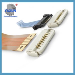
FC connectors are used to mate ribbon flat flexible cables (FFC) to PCB circuits in wire-to-board applications. FPC connectors connect flexible printed cables (FPC) to circuit boards. The wiring harness engineer in this article mainly introduces the basic information of FFC/FPC connectors.
FFC connectors are used to mate ribbon flat flexible cables (FFC) to PCB circuits in wire-to-board applications. They are also available in cable-to-cable configurations. These connectors feature high density and very narrow form factors to fit into tight spaces. They are commonly used in consumer applications such as laptops, cameras, computer peripherals, appliances and phones. Single- or dual-row connector housings are typically made of flexible plastic, polymer, engineered rubber, or film that surround the embedded metal connector. Available in a variety of locking styles.
FPC connectors connect flexible printed cables (FPC) to circuit boards. FPC is a type of FFC in which the conductors are printed on the cable substrate rather than embedded in it. FPC/FFC connectors are sometimes called ribbon connectors.
A key reason designers choose FFC/FPC connectors is their increased flexibility when used with flexible cables compared to traditional rigid circuit boards.
ELCO was an early developer of FFC-type connectors and merged with AVX in the early 1990s, with KYOCERA AVX assuming responsibility for ELCO products and continuing to develop its FFC/FPC range.
Although FFC became widely used in the 1970s, the cable was initially only available in direct solder or crimp contact versions. In 1986, ELCO invented the 8370 Series, the first cost-effective snap-on connectors to mate directly on FFCs.
The unique contact actuator design features retaining tabs to prevent accidental actuator separation. The retaining piece surrounds the actuator shaft and hooks onto the cavity, preventing the actuator from opening.
FFC/FPC Connector Design Notes
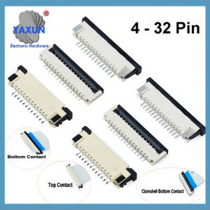
FFC/FPC connectors are available in pin, socket, snap edge and solder tab contact options with single or dual row housings.
Some variants have the ability to mix FFC cable and round wire contacts to provide a variety of spacings. For example 0.03 mm, 0.5 mm, 1.00 mm, 1.25 mm, 2.54 mm, but the most common spacings are 0.500 mm, 1.00 mm and 1.25 mm. A single FFC can have different spacing between different conductors on the same cable, but this is uncommon.
FFC/FPC connectors are available in fully shielded versions to control EMC interference.
Various locking mechanisms secure this connector type, including latches, pins, and retaining tabs.
Board termination options include surface mount or through hole.
0.5 mm pitch shielded FFC/FPC connectors feature one-hand auto-locking, high temperature resistance (125 °C), high-speed performance, and vertical or horizontal mating.
Applications of FFC/FPC connectors
Automotive, Consumer, Datacom/Telecommunications, Test & Measurement, Medical, Industrial
FFC/FFP connectors serve numerous markets and applications, including consumer devices, industrial controls, displays, printers, automotive, test and measurement instruments, appliances, and medical equipment.
See: FFC/FFP Connectors for Automotive Applications
FFC/FPC one-touch connectors feature single-step mating, an automatic locking mechanism and high retention force for reliable connections and easy operation. These connectors offer a visible release button for easy FFC/FPC cable release operation and a locking nail system to secure FFC/FPC cable connections with high retention force.