 English
 العربية
 Български
 Čeština
 Dansk
Dansk Nederlands
 Suomi
Suomi Français
 Deutsch
 Magyar
 Italiano
 日本語
日本語 한국어
한국어 Português
 Română
 Русский
 Slovenščina
 Español
 Svenska
 Tiếng Việt
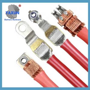
Comprehensive comparison of ultrasonic welding and U-type crimping wiring harness
I. Working principle
Ultrasonic welding
Through high-frequency mechanical vibration (usually 20kHz or 40kHz), the metal contact surface is rubbed to generate heat, and molecular fusion is achieved in the solid state. It belongs to solid phase welding technology. No current or high-temperature heat source is required to avoid oxidation and spatter problems.
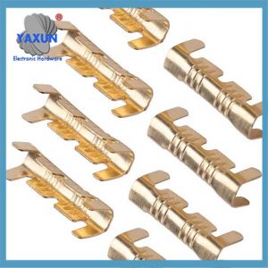 U Shape Copper Terminals Open Barrel Crimp Wire Cable Quick Wiring Butt Docking Connector Assortment Kit |
 High Quality U-Shape U Type Car Wiring Harness Connectors Copper Brass Crimp Joint Terminals for 6-10mm2 Cable |
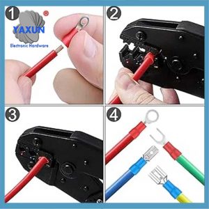 Wire Electrical Connectors Assortment Kit with Ring, Spade, Butt, Quick Disconnect, Crimp Wire Harnesses |
U-type crimping
Cold stamping of multiple wires using U-shaped terminals, mechanical connection through friction generated by physical deformation. The process is simple, but there may be tiny cavities inside due to insufficient deformation.
III. Process and cost
Equipment investment
The initial cost of ultrasonic welding machine is high (special welding head and high-precision parameter adjustment are required), but the long-term maintenance cost is low; U-type crimping equipment has low cost, but terminals and molds need to be replaced frequently.
Production efficiency
Ultrasonic welding has a fast speed (<1 second/point), which is suitable for mass production; U-type crimping requires manual assistance to adjust the position of the wire, and the efficiency is slightly lower.
Material requirements
Ultrasonic welding heads require special alloys with high wear resistance (such as titanium alloys), and the manufacturing process is complex; U-shaped terminals are mostly copper or aluminum alloys, with a high degree of standardization.
IV. Environmental protection and safety
Ultrasonic welding has no sparks, does not require solder or flux, and is in line with the trend of green manufacturing;
U-shaped crimping relies on physical deformation, and although it has no emissions, it requires the treatment of metal waste.
V. Typical application scenarios
Prioritized ultrasonic welding:
High-voltage wiring harnesses for new energy vehicles, on-board communication lines (such as CAN bus), precision sensor wiring harnesses, and other fields that have strict requirements for low resistance and high reliability. Prioritized U-shaped crimping:
Ordinary low-voltage wiring harnesses, low-cost vehicle wiring harnesses, and temporary repair scenarios.
Summary
Ultrasonic welding has more advantages in performance, durability, and environmental protection, but the cost is higher; U-shaped crimping is known for its economy and flexibility, and is suitable for conventional scenarios. The actual selection needs to be comprehensively evaluated in combination with specific process requirements, cost budgets, and product positioning.
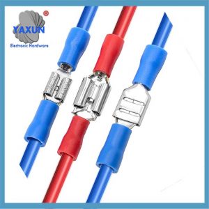 Insulated U-Type Fork Red-Blue Terminal Set Electrical Wire Cable Crimp Spade Ring Connector Assortment |
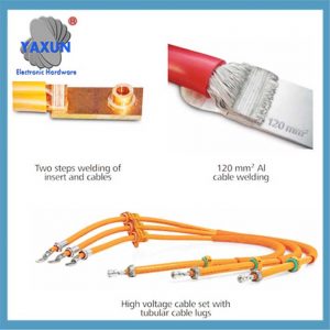
 Ultrasonic metal welding ofterminals with insulation crimp – erminal Welding Machine, Stripping and Crimping Machine |
 The Net Value of the Ultrasonic Metal Welding Process |
Ultrasonic welding and U-shaped crimping are widely used in the company as the two main methods of connecting automobile wiring harness wires. This article’s wiring harness engineer mainly introduces the two connection methods between wires, ultrasonic welding and U-shaped crimping, in automotive wiring harness production and manufacturing. A comparative analysis of the advantages and disadvantages of these two methods was conducted, which can provide a reference for the selection of connection methods between wires in the production process of automobile wiring harnesses.
As the functions of automotive electrical appliances become more and more complex, and there are more and more varieties, the wiring harness serves as the medium for signal transmission between various electrical appliances in the automobile. The loop relationships between wire harness wires are becoming more and more complex, and there are more and more check-in points between wires. Zum Beispiel, there are hundreds of stuck points in the cab wiring harness of heavy-duty trucks.
daher, the punching process is a very important part of the wire harness crimping process. Issues such as the selection of punching methods and the selection of punching equipment must be considered by wire harness process designers and even company production.
1 – The main methods and introduction of car wiring harness check-in
In the automotive wiring harness industry, punching refers to connecting the exposed copper wires after stripping off the insulation of each wire by welding or crimping to form a loop. The stuck point refers to the position where each wire harness is stuck. According to the position of the stuck point between the wires, the punching method can be divided into opening punching and docking punching.
Open punching means that the main line is a whole conductor and the clamping point is on the main line but not at both ends of the main line. The remaining wires are welded at the position where the main wire’s insulation is stripped off, so it is also called mid-stripping punch.
Butt punching means that the clamping point is at the end of the wire, and one end of the wire is connected to one end of other wires that need to be punched through crimping or welding. It can be one conductor and multiple conductors, or two or more conductors and multiple conductors. The wires in which both ends are involved in punching are called transition wires. Single-side punching is a special way of butt punching, that is, all wires are welded or crimped on the same side. The opening punch-in and docking punch-in are shown in Figure 1.
Figur 1, Schematic diagram of wire stripping and docking.
Depending on the equipment and principles, punching can be divided into two types: ultrasonic welding and U-shaped parts crimping.
Ultrasonic welding is a welding method that uses high-frequency mechanical vibration to recombine the surface of the welding material. It is a process between cold pressure welding and friction welding. It converts low-frequency electricity into high-frequency electricity, then converts high-frequency electrical energy into high-frequency mechanical vibration energy, and then transmits the high-frequency mechanical vibration energy to the surfaces of the two metals that need to be welded. And apply a vertical pressure on the welding surface, causing the two metal surfaces to rub against each other to generate heat energy to melt the metal, and under the short pressure, the melt will form a fusion between the molecular layers when the bonding surface solidifies.
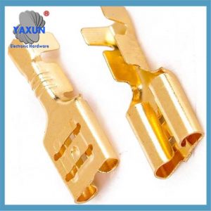
The principle of ultrasonic welding is shown in Figure 2. For U-shaped parts crimping, the U-shaped parts and crimping machine are selected based on the total wire diameter of the contacts. A special crimping die and jaws are developed for each type of U-shaped piece, and then two or more wires are cold-stamped together with the help of U-shaped piece crimping equipment. U-shaped piece crimping is a simple physical squeeze of the copper wire of the wire through the U-shaped part of the metal piece, and the surface friction between adjacent copper wires is used to ensure the connection between the wire and the U-shaped piece.
Figur 2 Schematic diagram of ultrasonic welding principle
2 – Comparative analysis of ultrasonic welding and U-shaped parts crimping
2.1 Comparative analysis of conductive properties
Voltage drop is an important indicator of the conductive performance of a wire. The so-called voltage drop refers to the potential difference formed across the resistor when current flows. According to Ohm’s law U=RI, when the current of the circuit is constant, the voltage is proportional to the resistance, that is, the larger the resistance, the greater the voltage drop, and the smaller the resistance, the smaller the voltage drop. The voltage drop U of an insulated conductor is calculated as:
U=IPL/A
(1) In the formula, U—voltage drop; P—resistivity; L—wire length; A—wire cross-sectional area.
U-shaped crimping is a simple extrusion of the copper wire of the conductor to cause physical deformation of the copper wire to create a connection through friction. Adjacent copper wires in the wire are still independent metal entities and cannot be in complete contact to form holes. The existence of these voids is inevitable, which will cause the resistivity P of the crimping part to increase, the voltage drop U to increase, and the conductivity to decrease, thereby reducing the transmission quality of electrical signals. Affect the normal operation of electrical and electronic equipment. After ultrasonic welding, the adjacent metals are fused into a whole, which results in a better density than the welding part of U-shaped parts. There will be no voids, the resistivity is low and close to zero, the voltage drop of ultrasonic welding is lower under the same conditions, and the conductivity and signal transmission quality are better. Zusätzlich, the ultrasonic welding part has a lower resistance than the U-shaped part crimping, which reduces the heat accumulation caused by contact resistance. To a certain extent, the quality hazard of wire harness burning caused by the local temperature increase of the wire harness is avoided.
2.2 Comparative analysis of usage scope
Ultrasonic welding is very effective in improving the signal transmission quality and current transmission capacity of wires, and can also improve the stability of automobile electrical systems. Zum Beispiel, wires with a cross-sectional area of 10 mm2 or more and Controller Area Network (CAN) wires generally require ultrasonic welding. Jedoch, ultrasonic vibration will destroy the coating. Copper surface coatings such as silver plating, zinc plating, tin plating, usw. can prevent oxidation and improve conductivity. Tin plating of copper wire has a great impact on ultrasonic welding. The melting points of tin and copper are very different. During welding, the tin layer is quickly in a molten state, thus blocking the combination of copper atoms and affecting the welding quality. For coated wires, U-shaped crimping is generally required.
2.3 Comparative analysis of welding quality
Ultrasonic welding materials have metal properties that are non-melting and non-brittle, and are minimally affected by external moisture, dust, oil and gas. It is not easy to cause corrosion, oxidation and other undesirable conditions in the copper wire, thereby avoiding the degradation of wire harness conductivity and signal transmission performance, and the reliability of stuck connection is high. There are residual stresses in the wire core at the crimping part of the U-shaped parts, and there is a risk of metal stamping rebound, and there is a risk of oxidation and rust under harsh working conditions. Not as reliable as ultrasonic welding. Ultrasonic welding has a rectangular shape at the welding point, with no loose core wires, broken ends or cracked core wires, and the wires are not bent and lead out straight from the fusion point. Ultrasonic welding may cause excessive welding flash and pierce the protective heat-shrinkable tube; the end of the wire core extends to overlap the wire insulation layer; the wire does not come out in a straight line from the fusion point; the wire core flies out and pierces the protective heat-shrinkable tube. A defective product caused by one or more broken core wires due to the welding process (generally, it is required that the number of missing core wires for each wire does not exceed 10%). When U-shaped parts are crimped, the wire core may fly out and pierce the protective heat shrink tube; the end of the wire core stretches to overlap the wire insulation layer; the wire sheath is pressed by the punching piece; the total diameter of the punching wire does not match the punching piece, usw.
2.4 Comparative analysis of costs
Ultrasonic welding requires metal materials with good toughness (small mechanical loss during sound wave transmission). daher, the most commonly used materials are aluminum alloy and titanium alloy. Jedoch, ultrasonic metal welding requires the welding head to be wear-resistant (higher hardness is required), which makes the selection of materials more difficult, because hardness and toughness are inherently opposed, which requires the selection of very high-quality steel materials. To maximize the effective life of the welding head, the cost is very high. The price of ultrasonic welding machines is generally higher than that of crimping machines, and the initial investment is higher. When using U-shaped crimping, a U-shaped piece is required for each clamping point in the harness. Wire harness products with many stuck points and large batches use a large number of U-shaped parts, resulting in high cumulative costs. Zum Beispiel, the price of U-shaped parts is 0.05 RMB/piece, and the number of cab wiring harness clamping points is 100 pieces/hanging, then the total cost of producing 1,000 cab wiring harness U-shaped parts is 5,000 RMB.
2.5 Comparative analysis of operability
Before ultrasonic welding and U-shaped parts crimping, it is necessary to sort out the stripped copper wires of the welded wires to avoid problems such as warped copper wires, burrs, scattered copper wires, and contamination with foreign matter.
During the ultrasonic welding process, the wires should be arranged vertically overlapping, and the large cross-sectional area wires should be close to the welding tool head below to ensure sufficient welding. The conductors should be placed against the anvil surface, snugly against each other, to provide sufficient solidity after welding. The length of conductor overlap should generally be between 5 mm and 7 mm. If the overlapping length is too short, it is difficult to ensure the welding strength. If the overlapping length is too long, the welding end will easily become warped, making it inconvenient for the next process. Oxidation, broken wires, defects and melting of the insulation layer are generally not allowed on the surface of the welding joint. The schematic diagram of ultrasonic welding operation is shown in Figure 3.
Figur 3, Schematic diagram of ultrasonic welding operation
U-shaped parts crimping production is fast and the equipment is simple. In principle, the number of crimped wires for U-shaped parts should not exceed 5. The recommended stacking order of wires is from thick to thin and from top to bottom. The conductor should be fully pressed into the crimped portion of the punch piece. The wire ends should be visible on both sides of the U-shaped piece and the length (C) from the insulation to the punching piece should not be greater than 3 mm, and the length of the wire core extending out of the punching piece should be 0≤B≤1 mm. The schematic diagram of the U-shaped component crimping operation is shown in Figure 4.
Figur 4, U-shaped parts crimping operation schematic diagram
3 – Summary
Ultrasonic welding has lower resistivity, smaller voltage drop, better electrical conductivity and higher reliability than U-shaped parts crimping, but it requires a large investment in equipment, the welding head is more expensive, and it cannot weld plated metals. U-shaped parts crimping has a wider range of applications than ultrasonic welding, and the equipment is simple and easy to operate. Jedoch, U-shaped parts use a lot of consumables. Compared with ultrasonic welding, U-shaped parts have higher resistivity, larger voltage drop, poorer conductivity, and poorer reliability. . Automotive wiring harness manufacturers should conduct a comprehensive evaluation of these two wire connection methods and make reasonable configurations. Jedoch, ultrasonic welding, as a new advanced welding technology, has obvious advantages such as superior conductivity and environmental protection, and is the development direction of automotive wire harness manufacturing.