 English
 العربية
 Български
 Čeština
 Dansk
Dansk Nederlands
 Suomi
Suomi Français
 Deutsch
 Magyar
 Italiano
 日本語
日本語 한국어
한국어 Português
 Română
 Русский
 Slovenščina
 Español
 Svenska
 Tiếng Việt
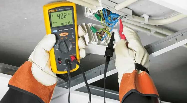
Continuity detection of connecting cables is a key step to ensure the integrity of the electrical connection of the internal conductors of the cable. Common methods and precautions are as follows:
1. Detection method
Multimeter detection method
Operation steps: Disconnect the power supply of the cable under test and adjust the multimeter to the resistance measurement range or the continuity test range (with buzzer prompt). Touch the test leads to the conductors at both ends of the cable. If the resistance is close to 0Ω or a buzzer sounds, it indicates continuity; if a high resistance value is displayed or there is no response, there is a breakpoint.
Applicable scenarios: Rapid detection of a single wire or simple circuit, often used in maintenance sites.
Continuity Detection Requirements for Connecting Cables
Special cable tester detection method
Principle: The tester sends a specific electrical signal (such as a pulse or voltage) at one end of the cable, and the other end receives the signal and analyzes its strength and integrity. If the signal is received normally and meets the preset parameters, the continuity is determined to be good.
Advantages: Suitable for batch detection of long-distance, multi-core cables, and can automatically determine the results and generate reports. Capacitance detection method
Technical implementation: By measuring the capacitance values at different positions of the cable (such as the first capacitance, the second capacitance, usw.), the continuity of the channel is judged in combination with the preset logic. Zum Beispiel, the continuity of the detector group and the extension cable can be comprehensively analyzed by multiple sets of capacitance parameters.
Application scenarios: High-precision detection of complex systems such as nuclear reactors can reduce the workload of manual maintenance.
2. Auxiliary detection methods Appearance and structure detection: Observe whether there is mechanical damage, oxidation or breakage on the surface of the cable, and confirm the integrity of the conductor in combination with cross-sectional analysis.
Mark continuity verification: Check the wear resistance and continuity of the cable markings to ensure that the marking interval meets the standard (such as the sheath marking interval ≤550mm).
TDR cable continuity tester fault location tracker
3. Precautions Safe operation: The power supply must be disconnected before testing to avoid the risk of electric shock.
Interference elimination: Electromagnetic interference may affect the tester results, and it is necessary to use a shielded environment or anti-interference equipment.
Combination of multiple methods: For key scenarios (such as nuclear facilities), it is recommended to combine capacitance detection, infrared imaging1 and physical testing to improve the accuracy of the results.
IV. Testing standards DC resistance verification: Indirectly judge continuity by measuring the conductor resistance value (converted to the 20℃ standard value). Abnormal resistance may indicate a breakpoint or material problem.
Process standardization: Enterprises should establish a “daily control and weekly investigation” system, combine training to improve the skills of testing personnel, and ensure process compliance.
Safety precautions
1. Employees must undergo training before they can start working.
2. Employees should abide by the “Production Safety Responsibility Management Regulations” during the production process and ensure safe production.
3. Description of safety hazards: The sheath has edges and corners.
4. Injury: Long-term plugging and unplugging will abrade the skin of the hands.
5. Precautions: Wear gloves during operation.
2. Precautions when using tools
Process flow ★In operation 3.1 Determine the wire harness detection method
3.2 Detect the wiring harness on the conduction stage (select one of the options in 3.3)
3.3 Manually detect the wiring harness (select one of the same as 3.2)
3.4 Inspect the wiring harness after repair 3.5 Protect the bare terminals (3.5 3.6 3.7 process operations are not in order)
3.6 Install accessories (protective shells, plugs, other accessories)
3.7 Protective plug-in 3.8 Coiled cable (it is strictly prohibited to step on the cable)
3.9 Packaging (the labeling on the packaging bag can be done in advance)
3.10 Turnaround ★After the operation, sign for confirmation and organize tools. 4. Process flow requirements 4.1 Determine the wire harness detection method (1) Quality requirements (characteristic classification/inspection frequency)
A. Materials that have a conductive relationship should be tested using a conduction table. Inspection frequency: 100% self-inspection, no recording; B. Materials that cannot be tested on the conduction table must be confirmed by the conduction relationship producer.
Characteristic classification: [B] Inspection frequency: 100% self-inspection, no recording;
(2) Process standards and requirements a. Shrink the material number to be detected on the conduction station, confirm whether the equipment conduction relationship file contains this material, confirm that the conduction relationship version number is consistent with the material to be detected, and press the conduction station inspection after confirmation Execute, as shown below;
B. If there is no conduction relationship, feedback to the production staff for confirmation of the conduction relationship. After confirmation, follow the manual inspection plan issued by the craftsman. Reasons for process requirements and response plan
(3) Reasons for process requirements and response plan a. Failure to confirm the material number and version number may lead to failure, resulting in the outflow of substandard products;
B. Failure to follow the manual inspection plan may lead to failure, resulting in the outflow of substandard products; response plan:
A. Re-conduct the test on the bench;
B. Reconfirm whether it can be detected on the conduction stage.
4.2 Conductive stage detection harness (conducting leads, box ruler)
(1)Quality requirements (characteristic classification/testing frequency)
A. The appearance of the wire harness complies with the “Visual Standard for Wire Harness Appearance Inspection” Inspection frequency: 100% self-inspection and record;
B. The accuracy of the circuit connection relationship is 100%, and there are no short circuits, open circuits, or wrong circuits. Characteristic classification:
【B】 Inspection frequency: 100% self-inspection and record.
(2) Process standards and requirements
1. Conduct item-by-item inspection and confirmation according to the requirements of the “Visual Standard for Wire Harness Appearance Inspection”;
2. After all the additional wires in the wiring harness are connected, conduct the conduction station test. During the test, insert them according to the position number of the sheath in the conduction relationship, as shown in the figure below;
3. The inspection program prompts “Test Passed” or “OK”, and the wiring harness has passed the inspection, as shown in the picture on the lower right. Remarks: 1. When the USB wire harness, luggage rack, support lamp, and strip lamp wire harness have a plug-in at the head and the other branches are bare terminals, insert the head plug-in and the last branch at the tail (bare terminal) into the testing station for inspection.
2. When a branch has multiple fuses, use a multimeter to measure and distinguish the fuse wire numbers, and then identify the correctness of the fuse model;
3. Before inspection, the ground terminal terminals need to be replaced with ones consistent with the model shown in the drawing to avoid errors in the actual model;
4. During the process of picking up and testing the wire harness, it is strictly forbidden to step on the wire when the wire harness is on the ground. Zum Beispiel, if there is a floor mat on the floor of the testing platform, the wire harness can fall on the floor mat, and it is strictly prohibited to step on the wire when it is on the ground.
(3) Reasons for process requirements and response plan
A. Failure to inspect as required can easily lead to quality issues, affecting assembly in subsequent processes or causing rework; B. Failure to insert the sheaths according to the conductive relationship, resulting in failed conduction and rework;
C. The prompt “Detection is correct” or “OK” means that the circuit inspection is qualified; response plan:
A. Adjust according to the requirements of the “Visual Standard for Wire Harness Appearance Inspection”;
B. Re-test after repair.
4.3 Manual inspection of wire harness (box ruler, multimeter, probe, paint pen, ballpoint pen) (1) Quality requirements (characteristic classification/inspection frequency)
A. The appearance of the wire harness complies with the “Visual Standard for Wire Harness Appearance Inspection” Inspection frequency: 100% self-inspection and record;
B. The accuracy of the circuit connection relationship is 100%, and there is no short circuit or open circuit. Characteristic classification:
【B】 Inspection frequency: 100% self-inspection and record.
(2) Process standards and requirements
1. Carry out item-by-item inspection and confirmation according to the requirements in the “Wire Harness Manual Continuation Inspection List”;
2. After inspection and confirmation, fill in the “Wire Harness Manual Continuation Inspection Form” and keep it;
Remarks: 1. Requirements for the use of multimeters: You cannot use multimeter pens to directly insert into the terminal pair jacks, and you cannot measure from the incoming end of the sheath (terminal insertion end). If the test pens cannot contact the terminal for measurement, use the thinnest probe (φ0 .65) Contact the terminal, and then touch the test lead to the probe to measure;
2. How to use the multimeter: Turn on the multimeter and select the buzzer alarm position (resistance on-off position). First connect the positive and negative poles and test to confirm whether the multimeter is normal. If the alarm is normal, then start the test. If an alarm occurs during the test, it means there is a connection. , does not display the value or does not alarm, indicating the difference; turn off the multimeter switch after use.
(3) Reasons for process requirements and response plan
A. Failure to inspect as required can easily lead to quality issues, affecting assembly in subsequent processes or causing repairs; B. Failure to insert the sheaths according to the conductive relationship, resulting in failed conduction and rework; Response plan:
A. Adjust according to the requirements of the “Visual Standard for Wire Harness Appearance Inspection”;
B. Re-test after repair.
4.4 Detect the wiring harness after repair (box ruler, multimeter, probe, red PVC tape)
(1)Quality requirements (characteristic classification/testing frequency)
A. Place unqualified products separately from qualified products and do not mix them. Characteristic classification:
【B】 Inspection frequency: 100% self-inspection, record
B. After a product with unqualified electrical performance is returned for repair, the electrical performance inspection must be carried out again. Characteristic classification:
【B】 Inspection frequency: 100% self-inspection, record
(2) Process standards and requirements
A. Unqualified products can be repaired on the inspection table. When it is necessary to go down to the inspection table for repair, stick a red tape on the problem area and place it in the unqualified area, as shown below; keep the red tape after repair, and then tear it off after being verified by the inspection personnel. Drop the red tape;
B. For defective products that affect electrical performance (dislocation, connection, open circuit, usw.), they must be inspected and confirmed again after repair; C. Record the problems of defective products.
(3) Reasons for process requirements and response plan
A. Mixing unqualified products can easily cause the outflow of unqualified products;
B. Failure to inspect and confirm after repair may easily lead to the outflow of substandard products;
C. Recording problems is helpful for problem analysis and reducing recurrence; response plan:
A. Separate and place unqualified products according to standards;
B. After repair, test again according to the original plan.
4.5 Protective bare terminals (PVC tape)
(1)Quality requirements (characteristic classification/testing frequency)
A. No leakage protection for bare wire terminals. Inspection frequency: 100% self-inspection, no recording;
B. There is no copper wire or terminal leakage after protection. Inspection frequency: 100% self-inspection, no recording;
(2) Process standards and requirements
Bare terminal model and appearance confirmation: Continuity inspection personnel check the correctness of the bare terminal model. If it cannot be confirmed, it will be reported back to the craftsman for confirmation. After checking that there is no deformation or damage in the appearance of the terminals and waterproof plugs, follow the protection requirements: bare wires and bare terminals of instrument wiring harness, chassis wiring harness, and electronic control wiring harness. A single wire (wire number) should be wrapped with 2 Zu 4 turns of tape for protection. No copper wires or terminals should be exposed, as shown in Figure 1. Top rack wire harnesses and other types of wire harnesses: The drawings indicate the types of self-contained parts, and the bare terminals (including bare wires) whose sheaths are not delivered as required. A single wire (wire number) needs to be wrapped with tape for 2 Zu 4 turns for protection, and no copper wire terminals are exposed. Other types of individual packaging protection, as shown in Figure 2.