 English
 العربية
 Български
 Čeština
 Dansk
Dansk Nederlands
 Suomi
Suomi Français
 Deutsch
 Magyar
 Italiano
 日本語
日本語 한국어
한국어 Português
 Română
 Русский
 Slovenščina
 Español
 Svenska
 Tiếng Việt
EB harness design method and assembly process can be systematically implemented in combination with software functions and process requirements, as follows:
1. EB harness design method
Modular configuration and multi-configuration management
Define multi-circuit solutions through EB Cable’s module configuration options, support harness design requirements with different configurations, and automatically generate 150% multi-configuration harness diagrams.
Use logical associations between configuration options to ensure design consistency, such as matching vehicle configuration with harness specifications.
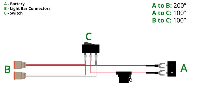
Cable Harness Assembly Component and Layout Guidelines – Dual Output 2-Pin Offroad Wiring Harness
Topology editing and 2D flattening
Flatten the 3D harness structure through a 3D software interface or manual topology editor to generate 2D drawings, optimize branch layout and length calculation.
Support branch direction definition (such as north, south, west, east, usw.) to improve wiring logic and readability.
Accessory and mounting rail association design
Use the accessory assistant to define the installation form and direction of the device and accessories, such as the associated installation of the motor protection switch and auxiliary contacts1.
The mounting rail allocation assistant automatically generates component layout based on the accessory configuration to reduce manual intervention.
Automatically generate production documents
Based on EB’s central database, quickly export component lists, cable lists and wiring tables to ensure that design and production data are consistent.
2. Key processes of wiring harness assembly Sub-material number production and inspection
Cut the wire size according to the positioning plate to avoid resource waste caused by size deviation, and ensure the quality of sub-material numbers through electrical testing and full inspection.
Wiring and branch management
Wiring is divided according to the drawings, and a single area is processed first and then cross-regional branches are processed, following the order from simple to difficult36.
The trunk branch needs to consider the tolerance (±5mm~±10mm) and the bending radius (≥2 times the harness diameter), and the process size is reserved to deal with assembly errors.
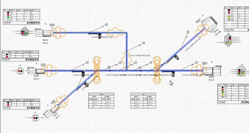
Software Aids Harness Design – Wire Harness Assembly, A Complete Guide to Types, Benefits, Manufacturing
Plug-in and fixing process
Perform the three steps of plug-in (push, listen, and pull back) to ensure that the terminal is in place and the connection is reliable7.
Use special tools to install bellows, sheaths and positioning parts to avoid damage or loosening of the harness78.
Testing and Inspection
The electrical test bench verifies the correctness of the circuit, and checks the terminal tolerance, wire binding uniformity and component assembly compliance in combination with the full inspection process.
High-voltage wire harnesses require extra attention to shielding performance (such as metal shell design, shielding ring) and dust and water resistance (above IP67).
3. Design-Assembly Collaborative Optimization
Data consistency: EB design data directly drives assembly process files (such as wiring tables, terminal diagrams), reducing information transmission errors.
Design for Manufacturability (DFM): Combined with EB’s configuration management function, assembly tolerances and process dimensions are reserved in the design stage to reduce rework rates.
Through the above methods, EB software can achieve a digital closed loop from design to assembly, improving the efficiency and quality of wire harness engineering.
In order to solve various problems in wire harness design, professional wire harness design software came into being. After years of development, the most widely used professional wire harness design software in the automotive industry currently include EB Cable from AUCOTEC of Germany and Capital (CHS) from Mentor Graphics of the United States. Both products have powerful functions and have a large number of customer groups in domestic and foreign markets. It can be called a mainstream wiring harness tool.
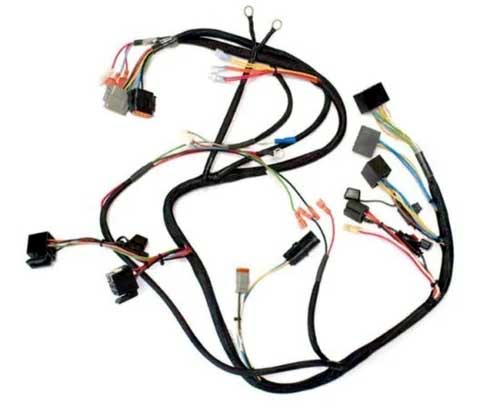
China Custom Wire Harness Assembly Prototypes and Manufacturing
EB Cable and Capital (CHS) are both designed and developed specifically for wire harnesses. With similar software architecture and design concepts, it can complete all work on automotive wiring harnesses from principle design to 2D wiring harness design.
Both EB Cable and Capital (CHS) software have the following features:
1. Use a central database to manage all data
2. Equipped with parts database, which can store symbols and parts data
3. Have collaborative design capabilities, with multiple engineers working on the same project at the same time
4. After the design is completed, various forms are automatically generated
5. Data can be automatically transferred during different stages of design. Schematic design data does not need to be repeatedly defined in the wiring harness diagram, saving a lot of work.
Modular (KSK) design can be achieved
6. Have data interface with 3D design software
7. Can solve some problems in production process
The author has only used EB Cable due to work reasons, so I will briefly share it below. The figure below is the design flow chart of EB Cable.
SYS system schematic diagram
EB Cable System Principle Design is an easy-to-learn and easy-to-use professional system schematic design tool based on electrical characteristics. Any electrical object in the design can be recognized by the software, and all electrical objects can be assigned material numbers. The connection of electrical objects is a physical connection.
The tree-like directory structure is convenient for browsing and querying, and the symbol library established in the symbol library can be directly called for drawing. Shortcut keys can be used to quickly position and zoom objects in the design. Mouse zoom, pan, and stroke commands are supported, making the operation simple and fast.
KAB wiring schematic diagram
The wiring schematic diagram is automatically generated based on the original system schematic diagram, the electrical component connectors are automatically generated, the wires are automatically generated, and the terminals, waterproof plugs and other accessories in the connectors are automatically generated.
2D wiring harness diagram design
EB uses the design data completed in the schematic diagram (including connectors, wire connections, terminal seals and configurations, usw.) to perform two-dimensional wire harness display. In this process, the data defined in the schematic diagram does not need to be defined again. daher, for two-dimensional wire harness design, you only need to define information such as wire harness topology, branch length, buckles and wrapping, and the circuit table, Anschlüsse, buckles, wrapping and other tables can be automatically generated. Automatically calculate wire length, branch diameter and other information, and all materials including terminals, seals, usw. can be viewed and output through the worksheet.4. Combine 3D wire harness model through HIM Pro
HIM Pro can realize data interaction between EBCable and CATIA. Through the interface, 3D wire harness data can be imported to automatically generate 2D wire harness diagrams, reducing repetitive manual drawing work. Gleichzeitig, information such as branch length in 3D design is fed back to EBCable, so that 2D wire harness design can obtain accurate wire harness branch length.
The three-dimensional data interactive interface provided by EB Cable is easy to operate and can intuitively display the differences between 3D and 2D wire harness design data. The interactive interface can scan and display 3D wire harness definition error prompts in real time, and objects in the CATIA 3D wire harness can be directly located from the prompts in the interactive interface, making it easier for engineers to quickly check design data and locate design errors.
The author himself summarizes several useful aspects of EB Cable based on his own actual experience:
1) Device library management function
• Device libraries can be quickly created in batches through Excel/CSV import.
• Devices can establish a one-to-one correspondence with symbols, and the same device can be equipped with multiple preferred symbols.l
• When engineers select devices, a warning will be issued if the device exceeds the company’s commonly used device library.
2) Table output function
• All data can be opened in the worksheet for unified management or viewing, and the worksheet operation is simple;
• All worksheets can be inserted into drawings or exported to Excel tables;
• Engineers can quickly locate the corresponding object through the search and link jump functions of the worksheet
• The worksheet provides a variety of data statistics functions to facilitate engineers to collect data
3) Data real-time link
Design data is correlated in real time at all stages of the EB Cable design process. When one data change occurs in the schematic diagram, wiring harness diagram, and statistical report, other related data will automatically change;
4) Three-dimensional interface HIM
• In the 3D wire harness design stage, the 3D interface HIM can be used to scan 3D wire harness data. The interface automatically counts and prompts errors in the three-dimensional wire harness design, and the three-dimensional wire harness can be quickly located and modified through the interface. The operation is very convenient and can avoid the transmission of 3D definition errors to the 2D wire harness design;
• Import the wire harness data in EB Cable into the 3D design, perform 3D wiring, and import the 3D design data to automatically generate a 2D wire harness diagram;
• After the wire harness design in EB Cable is completed, the diameter of each branch can be automatically calculated based on the thickness of the wires in the branch. The interface program can return branch diameter information to the 3D wire harness design and automatically update the thickness of the branches in the 3D design;