 English
 العربية
 Български
 Čeština
 Dansk
Dansk Nederlands
 Suomi
Suomi Français
 Deutsch
 Magyar
 Italiano
 日本語
日本語 한국어
한국어 Português
 Română
 Русский
 Slovenščina
 Español
 Svenska
 Tiếng Việt
Analysis of the wire harness overmolding process
I. Process Overview
Wire harness overmolding is a manufacturing process that uses injection molding technology to coat thermoplastic elastomers (TPE), silicone and other materials on the surface of the wire harness or connector to form an integrated structure. The core is to combine the coating material with the substrate (such as metal, plastic wire core) through the mold to achieve functional enhancement and structural integration. This process is widely used in the fields of automobiles, medical equipment, consumer electronics, jne. to improve the durability, sealing and environmental resistance of the product.
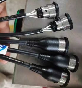
Wire harness overmolding process
II. Core wire harness overmolding process steps
Wire pretreatment
The wire core needs to be surface cleaned and burred, and the temperature resistance is checked to ensure that it meets the thermal processing requirements of the coating material.
Long wire harnesses (>50m) need to be drilled and stripped for subsequent positioning and fixing.
Mold design and positioning
Use pre-buried structures or tooling fixtures to achieve precise positioning of the wire harness in the mold cavity to prevent wire displacement or deformation during injection molding.
The mold needs to be designed with a pre-pressed sealing structure to balance the sealing pressure and wire protection (such as smooth transition chamfers to avoid crushing).
Injection molding
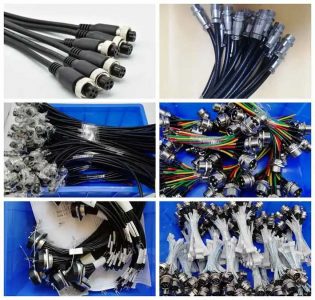
Insert molding: Put the pre-processed wire harness into the mold and complete the coating with a single injection molding. It has low cost but limited efficiency and is suitable for small batch production.
Multi-shot molding: Inject different materials in stages, suitable for complex structures and large-scale production, and the difference in thermal expansion coefficient of the materials needs to be controlled.
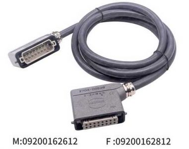
Aviation plug wiring harness welding overmolding process
Post-processing and testing
After cooling and finalization, check the thickness of the coating layer (usually ≤2mm) to avoid excessive thickness that may cause the wire harness to break easily or increase costs.
Verify sealing (such as IP protection level) and mechanical properties (such as tensile strength and wear resistance).
III. Technical advantages
Functional integration
Waterproof, dustproof (meeting IP certification standards) and anti-electromagnetic interference are achieved through sealing resin encapsulation, eliminating additional protective components.
Provide 360° strain relief function to enhance the tensile strength and impact resistance of the wire harness.
Performance Optimization
Coating materials (such as TPU and silicone) improve the high and low temperature resistance (-40℃~150℃), chemical corrosion resistance and flexibility of the wiring harness.
Reduce assembly processes, reduce labor costs, and are suitable for automated production.
IV. Key Challenges and Solutions
Material Compatibility
The temperature resistance and adhesion of the wire skin and the coating material need to be matched. Esimerkiksi, silicone coating requires the use of high temperature resistant wire core8.
Thermosetting materials (such as liquid silicone) need to control the injection temperature to avoid scalding the wire.
Process Control Difficulties
Sealing defects: Reduce burrs and overflow by adjusting the injection speed, pressure and mold temperature (such as lowering the material temperature to the lower limit of the material).
Wire damage: Optimize the mold pre-compression design and use special tooling to reduce the risk of indentation or offset.
Cost and yield
In the early stage of development, the scrap rate needs to be reduced through the pre-coating structure to reduce wire waste.
For large-scale production, multi-shot molding is preferred to balance equipment investment and efficiency.
V. Typical application areas
Automotive wiring harness: Seals, sensor wiring harnesses and interior parts are coated to improve oil and vibration resistance.
Medical equipment wiring harness: Catheter connectors and precision cables are coated to meet biocompatibility and sterilization requirements.
Industrial electronics terminal wiring harness: High-flexibility wiring harnesses (such as robot cables) are coated to enhance bending resistance and life.
What are the benefits of connector and wiring harness overmolding process
Yhteenveto
The wiring harness overmolding process achieves functional integration and performance enhancement through material compounding and precision injection molding technology, but its successful implementation depends on material adaptability, mold design optimization and process parameter control. In high-demand fields such as automobiles and medical care, this process has become a core solution to improve wiring harness reliability and production efficiency.
Overmolded connection harness is a collection of strings of wires and cables used to transmit power, information or operating signals. Overmolded Wire harness binding materials include clips, cable ties, sleeves, electrical tape, or a combination of these materials. In this article, the Overmolded wire harness engineer mainly talks about the wire harness assembly process and requirements.
Assembly process of connection harness
1. When making the wire harness sub-material number, the cutting line size must be determined according to the positioning plate.
In the current wire harness assembly process, the size of the sub-material number can often be met, but the size of the positioning plate cannot be met, resulting in a lot of unnecessary waste. Sub-material numbers also require electrical testing and full inspection.
2. Wiring harness routing.
① Lay out each sub-material number on the positioning plate according to the requirements of the drawing.
② When wiring, first place it area by area. After placing the sub-material numbers in a single area, place the sub-material numbers across areas.
③ For cross-region sub-material numbers, simple ones should be placed first, and then complex ones.
3. Insert the connector PIN (some TERs without PIN must be inserted into the corresponding connector first).
Wire tying (the tying position is according to the positioning plate, and the starting point of the tying is generally the starting point of the double line in the positioning plate).
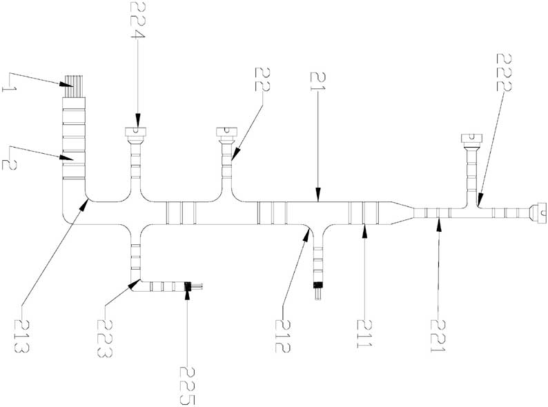
The wiring harness wiring structure of the control box in a certain equipment
4. Electrical test.
① Due to the complexity of the assembly line, the test data must be strictly checked.
② Testing can only be carried out after confirmation by PE & QE.
Engine wiring harness with integrated rubber boot
5. Full inspection.
① Check whether the terminal and CONN are within the tolerance zone.
② Check whether the wire binding ring is even.
③ Check whether the assembly method of parts is correct.
6. Warehouse the wiring harness sub-material number.
The sub-material number must be inspected and PASSed by OQC before subsequent actions can be taken.
Assembly process requirements:
1. After the wire harness is processed and assembled, all wire harnesses must be parallel and cannot move. However, the cable ties or zip ties must not snag the wires.
2. When inserting PIN or welding, the core wires cannot be twisted together, but they cannot be too tight.
3. When wiring, the terminals, HOUSING, D-SUB, IDC, and CONN of each sub-material number must match the markings on the positioning plate.
4. The wires of each sub-material number must be arranged according to the route on the positioning board.
5. When tying the line, the rope should move vertically from the bottom of the tying ring.
6. The cable tie should be tightened and the tail should not exceed 1mm.
7. When tying the line, the distance between the two tying rings should be about 25mm, and each rope should be tied to the end with a tail of about 10mm.
8. Tie a dead knot at the beginning and end of each rope.
9. When tying the wire, do not loop or wrap the rope. Do not jam the connector on the locating pegs and pull the cord hard. The thread end of the rope should be fixed on the locating nail and then tied. Otherwise, the terminal may easily break the core wire or the terminal may fall off.
Assembly quality standards:
After the wire harness is assembled into a finished product, the conductivity rate of the wire harness line must be tested to ensure that the conductivity rate is 100% and there are no short circuits or wrong circuits. Samaan aikaan, it must also meet the quality standards required by wire harness customers, and provide a safety and quality guarantee certificate when packaging.
Every step of the wire harness assembly and testing process strives to be meticulous, strive for excellence, and standardize operating requirements in accordance with the ISO 9001:2015 quality management system.